
BlinkenLights is a project which, simply put, turned the side of a building into a giant electronic mural. The technology behind BlinkenLights v1 wasn't overly complex, relying on relays to individually control a light behind each window of the office complex, in a giant 18x8 matrix.
Later the same group produced Arcade, a technically far more interesting approach using Matrix Control Units and solid state relays to control each light. What isn't mentioned is whether they're using SCRs & AC, or PWM & DC. Given the high power levels SCRs would make more sense.
[Image:live-arcade-quai-bird-large.jpg, Caption:Arcade in action, Alignment:center, Class:border, Size:Big]
Where do I fit into all this? Well I'm attempting to produce my own miniture BlinkenLights, using mulitplexed PWM, xmas tree lights, USB and a host PC to control it all.
Why do I want to make one of these?
Partly the sheer size, partly the exciting responses it generates from people, mainly just cos I can!
Technical Details
Oops, rows & cols labels are transposed
The 18 columns are driven by smaller 500mA Darlington transistors. As each row is taken low, each light to be activated has its corresponding column driver taken to saturation, connection it to the positive bulb supply. Different dimming levels can be achieved by controlling the off-time of each column driver.
This entire process happens approximately 50 times a second, meaning each row is only active for 2.5ms!
The Board
The board is a relatively large (compared to what I normally make) board, measuring 85x55mm. It has 28 active devices and 9 passives, along with a couple of connectors.
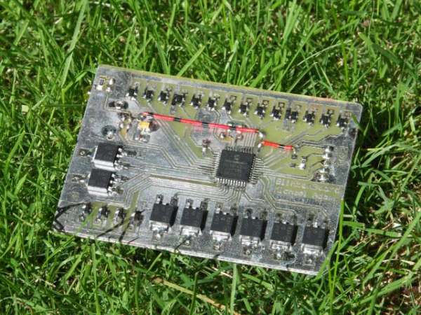
Freshly assembled PCB, 23rd Jan 2006
23/Jan/06 - At this stage it looks like I may've screwed up part of the design by not including any resistors in series with the base of each transistor. There may also be some thinking to do concerning the voltages at the collector of the column drivers.
24/Jan/06 - New board etched, this time with greater tolerances (still a bit close for comfort in some places) and series resistors on all the bases of the transistors! More or less the same layout, but with an extra 26 resistors (all 0805's too) and 4 diodes. There's nothing quite like soldering 0805's and SOT23's by hand!
25/jan/06 - Board is populated and working. Communicates over USB just fine. Some tweaking of the code was required; some bugs had crept in. Code is also more dynamic now. Only remaining issue is that the bulbs are very dim – going to look for some lower voltage bulbs. Failing that LEDs may have to be used, however this is suboptimal and I expect that each LED would need a series current limiting resisitor; not something I really want with 144 LEDs!